|
|
Joined: Jan 2014
Posts: 274
Member
|
|
Member
Joined: Jan 2014
Posts: 274 |
|
|
|
|
|
Joined: Mar 2015
Posts: 51
Junior Member
|
|
Junior Member
Joined: Mar 2015
Posts: 51 |
Hi Mega_mozg.
I have two questions to see if together we can solve everything. If you want to create a steering wheel with mmjoy, the type of assignment you have to configure? May be Rudder?.
Second, I have an hotas configured with 4 sensors and for the new steering wheel I want to use another Arduino promicro. When I set up a sensor in the steering wheel and connect the first (hotas) the same sensor don�t work in hotas. It is normal?.
a greeting.
|
|
|
|
|
Joined: Jan 2014
Posts: 274
Member
|
|
Member
Joined: Jan 2014
Posts: 274 |
Sak75
make unique PID/VID for your devices.
|
|
|
|
|
Joined: Mar 2015
Posts: 51
Junior Member
|
|
Junior Member
Joined: Mar 2015
Posts: 51 |
f**k is true, I'm idiot. Sorry!!!
|
|
|
|
|
Joined: Mar 2016
Posts: 2
Junior Member
|
|
Junior Member
Joined: Mar 2016
Posts: 2 |
I'm just starting to try and wrap my head around all of this. It's a lot to take in for someone who can, quite literally, just solder things together. I'm not very proficient with the idea of setting up circuit boards and inputs, etc. That said, I don't plan to stop learning and building till I get it right. So, as I said, I'm new to this, but I love the idea of using this software to try and work up a full set of controls. The big question that I have right now, is what about a load cell and strain gauges for the inputs on the joystick? I understand the general concept of how to wire it up, you have a surface the joystick presses into which creates a bending force - even slight - to the metal which registers as a change in resistance. I'm looking at this thread as a general reference on how it gets wired together: http://forums.eagle.ru/showthread.php?t=53887And if I understand that right, I would be going for #14 on that strain gauge list which means I would wire it like the diagram on the right-side of that list and place them so that each takes up approximately 1/4 the circumference. Those, if I understand this right, would go into some sort of bridge box... but that's where it loses me. Do I need a bridge box and how does that then wire into the rest of it? And does the MMJoy software even support that method?
Last edited by Psylence; 03/02/16 04:32 AM.
|
|
|
|
|
Joined: Oct 2014
Posts: 16
Junior Member
|
|
Junior Member
Joined: Oct 2014
Posts: 16 |
Psylence, (clever name btw) I have recently completed a load cell joystick "gimbal", using two 10kg load cells arranged in opposite axes of each other. Cells are fed into an INA125 load cell amplifier and outputs to the mmjoy2 board. It's my first version, but it works great for Star Citizen. Here's a few pics. http://imgur.com/a/02lyK
|
|
|
|
|
Joined: Mar 2016
Posts: 2
Junior Member
|
|
Junior Member
Joined: Mar 2016
Posts: 2 |
Euphoria, (Thanks. Your name is fitting considering it must be to fly with that setup) If I'm right, you're using something like this? https://www.sparkfun.com/products/13330I was thinking of trying something a bit more scaled down. Something more like: http://uk.rs-online.com/web/p/strain-gauges/0632168/But I'm still trying to work through it all still and I'm not set on anything. Funny as it is, my setup would be for Star Citizen as well and I'm also starting with a Cougar HOTAS. I'm guessing that what I do is attach those to say, a pipe which is fitted about the Cougar stick with a slight gap(to give me let's say 1/8 inch of play all the way around), then the gauges which are spaced about on X+, X-, Y+, Y- axes, run into an amplifier and outputs to my board(I'm thinking of using a flashed Pro Micro). That's where I'm a bit at a loss though, how do I set up the amplifier properly and how would I output to the board properly? Again, if I understand this right, I would combine them into 2 sets of 2 sensors(1 set X, 1 set Y) and wire them to say a load sensor combinator to make it easy for me: https://www.sparkfun.com/products/13281Where each set of 2 would share one wire that would go to the R(Excitation) and the other two would go to W(Output +) and B(Output -). That would then connect to a load cell amplifier: https://www.sparkfun.com/products/13230Which would wire to my board VCC -> 5v, CLK -> Digital pin, DAT -> Different Digital Pin, and GND -> GND. Is that right?
Last edited by Psylence; 03/03/16 08:32 PM.
|
|
|
|
|
Joined: Feb 2016
Posts: 2
Junior Member
|
|
Junior Member
Joined: Feb 2016
Posts: 2 |
I have founf out that the mmjoy firmware wasnt uploaded to the Board,due to a problem in the bootloader mode.
When I enter COM port it goes green and I can do the upload even though without success,
when I put it in bootloader mode it goes off like its not recognized and doesnt allow me to do the install at all.
It is inverted with few words,is anyone able to help on this?
|
|
|
|
|
Joined: Nov 2001
Posts: 3,960
Senior Member
|
|
Senior Member
Joined: Nov 2001
Posts: 3,960 |
Any of the compatible boards models (link in OP topic).
Based on connections with Arduino Leonardo PRO Micro - the model with less pins there:
http://simhq.com/forum/ubbthreads.php/topics/4118815/Re:_MMJoy_-_Build_your_own_USB#Post4118815
The TLE501x connections, as are done in digital mode share 3 pins on board, plus 1 pin for each axis input (8) = 11 pins.
This leave you with 9 pins for set the matrix, e.g 4x5 = 20 buttons
5 encoders will take 10 buttons positions, so can wire up to 10 buttons/switches more.
Teensy ++2.0 have more pins available and can reach 64 buttons (8x8 matrix) - remember that Windows see up to 32.
I suggest buy Teensy or Sparkfun boards due their better build quality over Chinese clones - despite these work OK (I use 3).
|
|
|
|
|
Joined: Nov 2001
Posts: 3,960
Senior Member
|
|
Senior Member
Joined: Nov 2001
Posts: 3,960 |
PJRC is OK or www.sparkfun.com.In this Arduino Boards, the mc ATMEGA32u4 have a 10 bits ADC for analog axis (pot/sensor) inputs. The TLE501x have build in ADC 12 bits and send signal for board in digital way, in this case his resolution prevail.
|
|
|
|
|
Joined: Nov 2001
Posts: 3,960
Senior Member
|
|
Senior Member
Joined: Nov 2001
Posts: 3,960 |
Yes, 12 bits but get the TLE5011 (last model). A practical way to connect is use 2.54"connector header bar (female, 40 pins), then cut* in appropriated size and solder the wires in this bar pins - can use heath shrink to reinforce/protect the solders and looks nice - and plug the bar in Teensy connectors. Result "PnP". BU0836 include this connectors. * Or buy in appropriated size (4, 8, 10...) Sample: http://core-electronics.com.au/0-100-2-54-mm-female-header-1x16-pin-straight.htmlBTW - Combining with the male header bar can make nice connector plugs (not for Teensy, but for other use). http://core-electronics.com.au/header-40-pin-male-long-centered-pth-0-1.html?___SID=UDont make solder direct in Teensy pins, the temperature and current transients of solder iron can kill then. I am not fan of breadboard (other for experimentation), this result in a mess of wires that can induce electrical noise. Since Teensy is tiny what can help is make a support PCB with more pins. But for your project is not really needed. For cables is recommend the "pig tail" type (multi copper wires with Teflon like insulation) used in telephony. Dont know the technical name - never see one.  See in Mega_MOZG pictures: http://simhq.com/forum/files/usergals/2015/03/full-37484-99124-dscf5909.jpg
Last edited by Sokol1; 03/07/16 06:41 PM.
|
|
|
|
|
Joined: Nov 2001
Posts: 3,960
Senior Member
|
|
Senior Member
Joined: Nov 2001
Posts: 3,960 |
This support board model don't include button matrix, just expand the Arduino board pins, e.g. instead share +5V pin for all axis inputs you have one pin for every axis, etc.
If you will use few buttons, e.g. ~10, is more practical just put the diode in one pin of every switch.
Last edited by Sokol1; 03/08/16 10:26 PM.
|
|
|
|
|
Joined: Nov 2001
Posts: 3,960
Senior Member
|
|
Senior Member
Joined: Nov 2001
Posts: 3,960 |
Is simple, e.g. a 2x2 matrix (lines and columns pins in controller board) handle 4 buttons. Mean that every line is shared with 2 buttons and in same way every column is shared with 2 buttons.  upload image online free upload image online freeThe diodes, as explained in the link is for avoid keyboard ghosting with 3 or more buttons pressed simultaneous. They made the current flow only in one direction.
|
|
|
|
|
Joined: Jan 2014
Posts: 274
Member
|
|
Member
Joined: Jan 2014
Posts: 274 |
I think I read it earlier, but as I understand it, it's possible to have MMJoy send one pulse when a switch is turned on, and then one pulse when i'ts switched of again. Correct? Mode "Switch" one pulse when "on to off" or "off to on".
|
|
|
|
|
Joined: Mar 2016
Posts: 5
Junior Member
|
|
Junior Member
Joined: Mar 2016
Posts: 5 |
hi sokol.i dont upload frimware  i need a vedio from upload frimware arduino leonardo.tnx 
|
|
|
|
|
Joined: Mar 2016
Posts: 5
Junior Member
|
|
Junior Member
Joined: Mar 2016
Posts: 5 |
Success!! yeah
I can program it successfully now. thumbsup
It could be possible settings mmjoy2(20151118) for 4-axis and 4 encoder and 10 button give me
|
|
|
|
|
Joined: Mar 2016
Posts: 5
Junior Member
|
|
Junior Member
Joined: Mar 2016
Posts: 5 |
I need Leonardo schematic like pic below 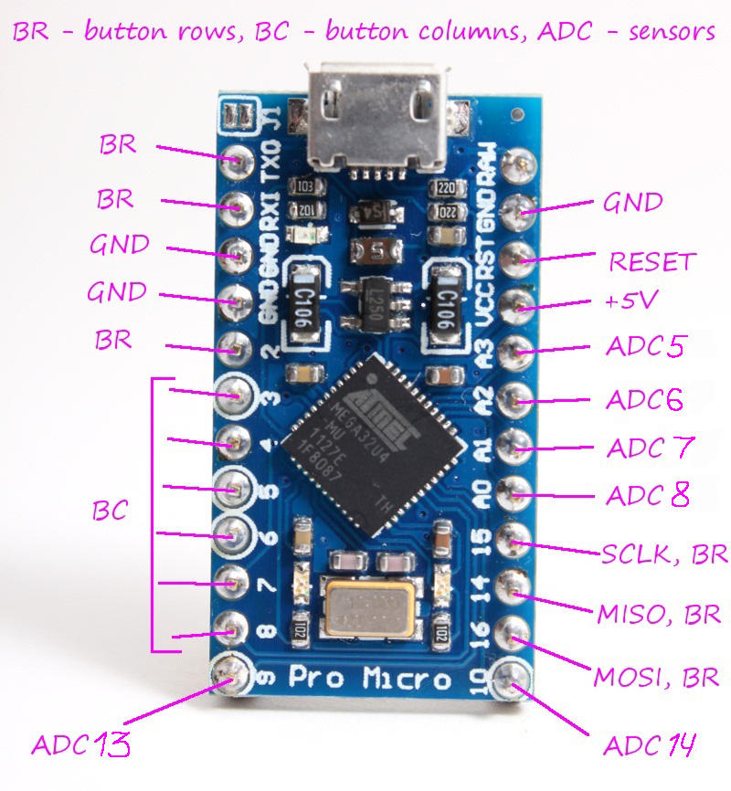 can you help me?
|
|
|
|
|
Joined: Nov 2001
Posts: 3,960
Senior Member
|
|
Senior Member
Joined: Nov 2001
Posts: 3,960 |
This?  http://simhq.com/forum/ubbthreads.php/topics/3994326/Re:_MMJoy_-_Build_your_own_USB#Post3994326
Last edited by Sokol1; 03/12/16 11:55 PM.
|
|
|
|
|
|
|
|
|
|
|
|
|
|
|
|
|
HOA's
by Terl9999 - 09/18/26 04:12 AM
|
Football
by Terl9999 - 09/18/26 02:42 AM
|
Flags
by Terl9999 - 09/15/26 10:03 PM
|
|
|
|