My stick was not calibrating properly....to cut a long story short I took it apart and could see that a couple of the wires (black and red) that go from the Base PS2 connector (female) had come away from the soldered interfaces which are routed down to the 6-pin connector on the circuit board.
Does anyone know the correct coloured wire mappings from the circuit board to the female PS2 socket?....or know of any internal diagrams/photos that show this? I've searched these forums and googled it but haven't come up with anything shows it.
What I'm looking for are mappings of these wires:-
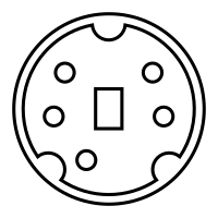
into the pins on this connector:-
Last edited by Paradaz; 12/27/1205:16 PM.
On the Eighth day God created Paratroopers and the Devil stood to attention.
I doubt it's under warranty as it got it on release but if I can get the pin-outs, it's a 10 minute job just to solder them back on.
It was my doing, as I went to unscrew my stick extension and it twisted the attached hall sensor by 90 degrees which is why the internal wires popped out.
If I can't fix it I'll have no other option but to sell the handle as a seperate item, and either try and replace or buy the whole thing again which I'm not keen on doing as I can only see them for about �300
Alternatively, is there anyone in this forum who can unscrew the A10 joystick handle of their base unit, and unscrew the 2 small screws off the female PS2 interface and tell me what order the colours go in? There should be just enough slack to see. In the second picture on my first post, it's just a matter of unscrewing the 2 visible screws.
Thanks to anyone in advance who could do this for me. The warthog has a 5-pin connection,the diagram below is showing the male version connector so when you look at your warthog base, the blank pin will be on the bottom left.
On the Eighth day God created Paratroopers and the Devil stood to attention.
I'll be happy to pull one apart and photograph it for you tomorrow if you like.
In the meantime...I am 99.999999% sure that black will be ground...so if you have a voltmeter (well, resistance meter) you should be able to find that one of the solder connections is continuous with the metal casing on the PS2 connector and that would therefore be the ground / black wire.
It takes a real sadist to make a circuit / cable connection where the only black wire isn't ground.
In the meantime...I am 99.999999% sure that black will be ground...so if you have a voltmeter (well, resistance meter) you should be able to find that one of the solder connections is continuous with the metal casing on the PS2 connector and that would therefore be the ground / black wire.
It takes a real sadist to make a circuit / cable connection where the only black wire isn't ground.
The thing is......there are 2 black, there is an obvious (slightly thicker one) soldered to the casing (ground)which comes from the common ground at the base of the joystick unit, but there is another that is connected to one of the mini-din pins. (not helpful!)
A photo of a fully functional one would be great, or a description of pin numbers 1-5 and the associated colour. If you do this please tell me how you're reading the pin numbers lol i.e number one starting clockwise from blank pin etc, thanks in advance.
On the Eighth day God created Paratroopers and the Devil stood to attention.
I'm having a tough time getting a picture that shows the wiring properly. How's this?
First, I recommend disassembling the stick a little more completely - the wires get pinched/pulled/cut if you try to work with the ball joint without doing so. Look at the inside of the base, and take a picture before you start if you need to. Unplug the cables in there. See the the black plastic center section that's held in by 2 screws? Remove the screws and lift that section out. That's the Hall sensor. Now if you look inside, you'll see the magnet that the Hall sensor reads. Use forceps or a needle nose pliers and lift the magnet out (no need to grab the round magnet directly - grab the pez-candy sized plastic piece around it. It just lifts out - friction fit. If you have to pull hard, you're doing it wrong.
It's now much easier/safer to lift off the top half of the ball joint to work on your wiring.
Back to your specific question...if I hold the connector up so that I'm looking at the solder side of the part, and put the thicker black wire that connects to the metal case up top at 12:00, then going around clockwise I see
thick black (12:00) grounding wire yellow red (3:00) thin black (6:00) gray orange (10:00)
That's perfect, thanks Teej....very much appreciated. I had already completely disassembled the whole unit and will be re-greasing etc once the soldering is done.
Going from part guesswork I had the yellow, orange and grey (mine is brown) correct but the red and black the wrong way round so good job I didn't solder and then test it. Hopefully I can get this back on its feet now otherwise I'll have an expensive paperweight.
On the Eighth day God created Paratroopers and the Devil stood to attention.
Thanks Teej I just had the exact same accident that Paradaz had 5 years ago as I was cleaning my WH. Was full of dirt after 6+ years of jntense flying.
Unfortunately I did not. The joystick is not recognized by Windows when I plug it in. It worked long enough that I could check the buttons and axis so the wire-fix worked. I think the magnet fell down on the hall sensor during this testing and the electronics somehow died. I had fastened it with Locktite glue just in case to prevent this from happening but it fell down anyway. I'm flying with a lousy Cyborg3D now and it's torture.
Buy Baur, VirPil or VKB base and use Warthog grip in then.
I took your advice, Sokol. I had to wait until last spring though before Gunfighter II Pro + MCG Pro were available. I love it. Buttkicker is under the chair of course.
I'm still waiting for a Warthog grip adapter. Don't get me wrong, MCG Pro is fine and probably more versatile (I'm using it for mouse X ,Y & mousewheel) , but I'm missing the cold steel feel in my hand.
Although I fixed my Warthog in the end, I have since snapped the actual metal stick low down in the shaft...to that end I have a spare working base and no real use for it. To get the best of both worlds I ended up buying a Virpil T-50 base and screwing my other Warthog handle onto it and haven't looked back. On reflection, for such a quality bit of functionality that the Warthog offers, the gimbal/plastic dome doesn't belong in there and the stiction and centering is probably one of the most complained about parts of that particular hardware. I think Thrustmaster missed the beat with that and hopefully will have learned from that mistake in future products.
On the Eighth day God created Paratroopers and the Devil stood to attention.