Forum Archives » Complete » EAW » How to Make an Instrument Panel
Page 1 of 5 1 2 3 4 5 >
Topic Options
Hop to:
#2418866 - 01/09/08 01:36 PM How to Make an Instrument Panel
Crashin' Jack Offline
Member

Registered: 10/02/03
Loc: Chicago
Similar to Col. Gibbon's Skunkworks Thread, I'd like to show you haw to make a new instrument panel as I go through all of the steps. Srea is working on a new version of the Me-163 and asked me to help, so I thought I would use this as my example.

Sera sent me only the Instrument Panel file in the Me109K slot, which is the P109KX.3DZ and TPC file. I looked through my collection and found the aircraft he is starting with, which is the Firm's Me-163. I loaded up the panel with the rest of the model to see what I am starting with:


Pretty good for it's day, but some of the needles are off and the instrument faces are a bit fuzzy. The biggest question in my mind at this point is also, how accurate is it? So off to the web and other resources to find photos to see if I can confirnm this is a correct cockpit. I also have a considerable collection of research material on my hard drive, and I found a series of photos that confirm this is an accurate depiction of the Me-163:


When checking sources, I recommend going far beyond a single photo; make is a thorough search. Many times the configuration changes from one mark to the next. In Japanese cockpits, pilots were actually allowed to customize their cockpits to the extent of actually leaving out gauges! So, spend a few more minutes searching and your efforts will be rewarded.

The next step is identifying the gauges. This can be difficult. Russian gauges in particular, as they are unique in design. I have an extensive collection of information and can be used as a reource if needed. I have also made a number of gauges available on my addon page at Tally Ho.

Going back to my references on my hard drive, I found this image:


This is a remanufactured display version of the Me-163 cockpit, and although it is a bit too shiny and some of the stuff seems to be psuedo reproductions, the layout is correct and the gauges are for the most part original. (I'm sorry but I couldn't find the original website for these images.) Even on this site there were several alternatives for the blind flying panel, which is the central "raised panel" area with the most critical instruments mounted on it. In addition, this website had some great photos of the origianl instruments:


The urge to simply paste these images into the pcx file is overwhelming as they are fine close ups, so I airbrush out the needles and get rid of the white background, and give it a try. This is the result:


I would daresay the original looked better. There are a number of reasons why this simply doesn't work,palettes and conversion problems being the top two. But fortunately we can make our own - if you have Photoshop. The same technique may be available in Paint Shop Pro, but I have not investigated it.

I'll leave that for the next lesson.
_________________________
"Blasts from clustered R4M quartets in my snout
And see these English planes go burn...." Blue Oyster Cult

http://members.aol.com/brokenputer/crashin_jack.htm

http://www.sandbaggereaw.com/crashinjack.html


Top Bookmark and Share
#2419017 - 01/09/08 04:55 PM Re: How to Make an Instrument Panel [Re: Crashin' Jack]
Fran_Zee Offline
Member

Registered: 01/15/04
Loc: Bavaria
CJ, old friend, let me help you:

http://www.cockpitinstrumente.de/Flugzeu...%20Cockpits.htm

Go to "Jäger" (=fighter) then to Messerschmitt Me 163 - then you´ll get the different "Komet" versions. The page is in german, unfortunetely (for you ;\) ), I can translate for you if there´s need of

Good idea - I´m looking forward to yout workshop reports
_________________________
Greetings

Fran

"Give beer to those who are perishing, wine to those who are in anguish;
let them drink and forget their poverty and remember their misery no more."

(Proverbs 31:6-7)


Top Bookmark and Share

#2419066 - 01/09/08 06:20 PM Re: How to Make an Instrument Panel [Re: Fran_Zee]
Ecv56SERA Offline
Member

Registered: 10/19/04
Loc: Argentina


_________________________
FOREVER EAW.!

Top Bookmark and Share
#2419335 - 01/10/08 01:35 AM Re: How to Make an Instrument Panel [Re: Ecv56SERA]
Crashin' Jack Offline
Member

Registered: 10/02/03
Loc: Chicago
Fan_Zee, thanks for the post; I already have that entire site pretty much downloaded, LOL! It's a truly awesome site, and I swear that at least part of it was in English when I first found it.

Sera, thanks for the images, I think they will be quite useful! You wouldn't happen to have an interpretation of the language in the last image, would you? Or at least which language?

The fourth image above also brings up a point I would really like to stress. I do not recommend using another game as a reference. I have found in other games that a certain license is taken to make things easier, cockpits are sometimes copied from one aircraft to another, and I have even found a Russian aircraft with gauges in English. I am not trying to put these cockpits down in any way, as they are all finely done, but personally I prefer to work from original World War II photos as my source. Sometimes the other games happen to provide a clearer view of something you know is correct, like trying to get the spelling correct in a language you are not familiar with. But if you are trying to be accurate, be skeptical! This includes WWII documentation. I always like to get at least one confirmation.
_________________________
"Blasts from clustered R4M quartets in my snout
And see these English planes go burn...." Blue Oyster Cult

http://members.aol.com/brokenputer/crashin_jack.htm

http://www.sandbaggereaw.com/crashinjack.html

Top Bookmark and Share
#2419488 - 01/10/08 06:09 AM Re: How to Make an Instrument Panel [Re: Crashin' Jack]
Weird_Crapolla Offline
Member

Registered: 12/11/06
Loc: St Barth
Hi,

Language = Czech \:\)
So ... Pisis ... where are you .... ?

OFF
_________________________
Flying is the perfect vocation for a man who wants to feel like a boy, but not for one who still is.
WIKI (EAW Encyclopedia)

Top Bookmark and Share
#2419489 - 01/10/08 06:11 AM Re: How to Make an Instrument Panel [Re: Crashin' Jack]
Crashin' Jack Offline
Member

Registered: 10/02/03
Loc: Chicago
HOW TO MAKE A NEW GAUGE FACE

This is something that had really thrown me. How do you make a whole bunch of "tick" marks, following different radi, in a circle when you can barely draw a straight line? I found this thread which explained it all in a brilliant, simple way at a forum called "Simmers Paint Shop:"

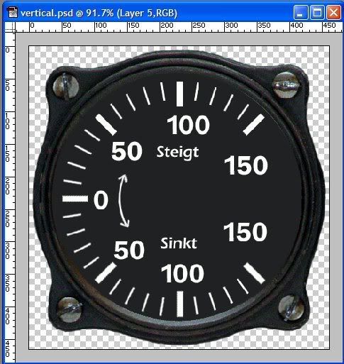
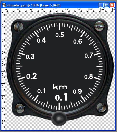
http://www.simmerspaintshop.com/forums/general/471-making-gauge-art.html

I will expand on that idea in a minute. First I decide which gauge I want to do. Looking at my references, I have chosen the Vertical gauge, as it is symetrical, not too many tick marks, and pretty straight forward:


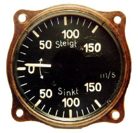
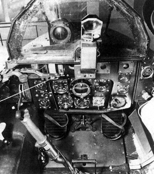
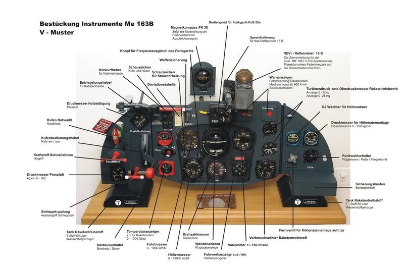
By the way, there are lots of good sources on the net for finding gauges, even of World War II vintage. There are many places that specialize in selling gauges as collector's items, for vintage aircraft, and so on. Even auction sites like eBay can yeild good results. All you need is something you can read.

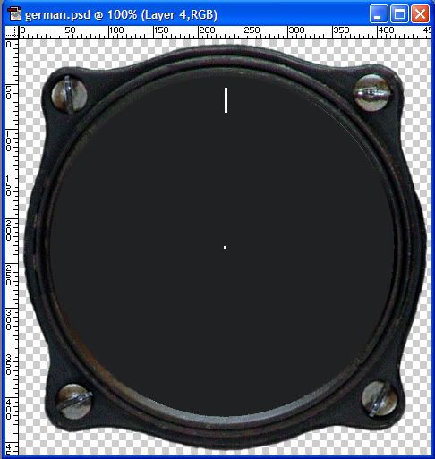
The first step is to create the gauge case. Different countries tend to use a similar design; one case can go a long way! What you are looking for is a good case that has a nice combination of shadow and highlight detail, with a nice smooth finish. Select and cut or delete the background outside of the gauge away, as well as any open screw holes. If there are screws in place, leave them as is. Now carefully paint the inside of the gauge a very dark gray. Don't use black, as it is "too black" when you are done. Adding some noise to the dial face adds a bit of softness to it that is nice. I don't generally add any highlights to the gauge face; this hasn't worked so well when viewed "in game." We want to have very clear detail when we are through. Here is an example of a German case I have made using the above procedure:


Feel free to use this for your own projects! When you make a case like this, try to center it in the image as much as possible, and make SURE the image size is an odd number in both directions. now zoom in to the center of the picture, add a new layer to the image, and place a dot in the exact center of the image. Now you will have an even amount of space on either side, and top and bottom. Let's say your image is 201 pixels across and 215 pixels top to bottom. Now you have 100 pixels on each side of the dot, and 107 top and bottom. If your image was even, you would have 99 on one side, and 100 on the other, 106 on the top and 107 on the bottom. For the next step, this dot placement is critical or by the time you are finished you will have a skewed image.

In Photoshop, when I place the dot, I like to use the second smallest dot on the tool options menu; this dot is actually 3x3 pixels, is easier to work with, and will still be centered.

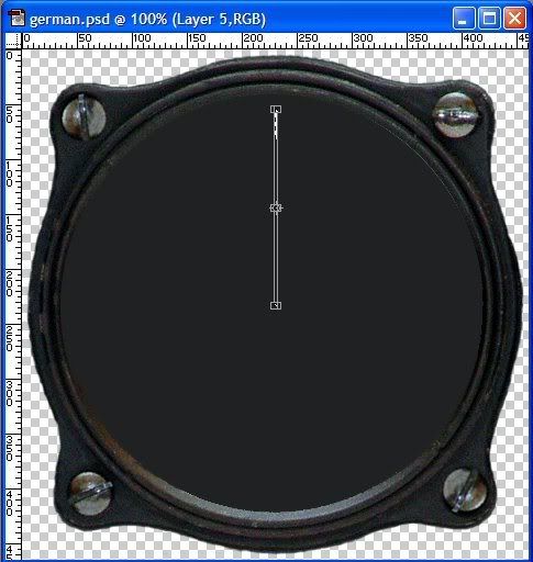
Now go to top dead center and draw a line for your first tick mark. You should have an image, that looks like this:


Now look at the origianl gauge. You need to determine what the degrees between each tick mark is. Don't worry, it's easier than you think. If you look at the vertical gauge, you'll notice that there is an area where the tick marks are missing on the right side. Since this gauge isn't a full circle gauge, we'll use the half circle instead. You can see there is a heavy tick mark straight up at the top, as well as one directly below it on the bottom. This is 180 degrees. Count the tick marks on the left side; you will see there are 20 tick marks (21 counting the top dead center; but we have made that one already). 180 divided by 20 is 9. So the difference is 9 degrees.

Go back to your new gauge in Photoshop, and select the dot in the center using the Magic Wand selection tool. Hold down the Shift key and select the tick mark as well. Create a new layer, and go to the menu bar under "Select," and choose "Transform Selection." Now you will have an image like this:


Look closely at the Transform Toolbar and you should see this:


Notice the two options circled in red. The one on the left is a series of boxes. This will change as you make you way around the gauge face. It is the relationship of the central pivot point - the dot - to the end if radial segment - the tick mark. This will be apparent when you come to it. To start, though, select the bottom center.

In the second red box, just after the little triangle, put in the degrees you want to turn the image. In this case, it is 9. As soon as you enter a value here, you will see your selection shift to a new position. You should now see this image:


Slect the Paintbucket tool, and a window will pop up asking if you want to apply the transformation. Click on "Apply" and paint the selected area white with the paintbucket tool.

To do the next tick mark, go to "Selection" in the toolbar meny, select "Transform Selection" again. Now you will see a wide rectangle. Do everything as you did before, except now in the small grid of boxes select the one in the lower left. "9" will still be the degrees.

There is an alternative to the above. You can go back to the original tick mark and dot, select them and add 9 to the degrees each time, so you end up with 9, then 18, 27 and so on. This can be more accurate, especially if you have very fine lines with a small degree of movement.

To move to the left of top dead center, use "negative" numbers, i.e. "-9" instead of "9."

I like to do the heavy tick marks after the thinner ones, but they are done in the same way; just use a larger step in between.

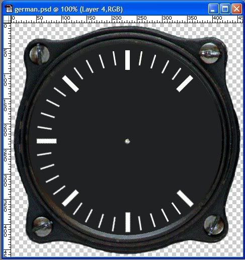
After a while, you should have an image that looks like this:


Now go back to the orginal tick mark, make a larger heavier one, and repeat the procees for the heavier marks. In this case, you will move the transform 9x5 or 45 dgrees for each mark. The end result should be this:


Now add in appropriate text, and the little up and down arrow, and you have this:


Note: I drew the arrow by hand, but there is a really great tutorial on drawing arcs here:

http://www.thegoldenmean.com/technique/pen3.html

So, there you go, one Vertical gauge ready to go. It is still in PSD form, and I hope you left all the layers as they were. You never know when you might want to use a part of it. Also, if you look closely, you will see that the tick marks aren't quite centered. Go through the layers and adjust everything up a little and it will look much better.

Store this gauge away and move on to the next. After you do this for awhile, you will have a pretty good library, and hopefully for the next project you only have to make a few gauges. Or better yet, send them off to Tally Ho for others to use!

Okay, I need a break. Give that stuff a go, and please post any questions.

Cheers!
_________________________
"Blasts from clustered R4M quartets in my snout
And see these English planes go burn...." Blue Oyster Cult

http://members.aol.com/brokenputer/crashin_jack.htm

http://www.sandbaggereaw.com/crashinjack.html

Top Bookmark and Share
#2420290 - 01/11/08 06:04 PM Re: How to Make an Instrument Panel [Re: Crashin' Jack]
Ecv56SERA Offline
Member

Registered: 10/19/04
Loc: Argentina
I am impressed with their great work CJ!
Can you include this work inside the eaw?
Does the me163 have 13 active gauges approximately in the panel of instruments, can you make them to all with this technique and to include them inside the 256X256 pcx?
I am very retailer with my cockpits, in the case of the me163, I work a lot so that this it is real, at least in structure 3d, but you not to make good unstrumentos, their help is fantastic!
My work:


_________________________
FOREVER EAW.!

Top Bookmark and Share

#2420668 - 01/12/08 01:36 AM Re: How to Make an Instrument Panel [Re: Ecv56SERA]
Crashin' Jack Offline
Member

Registered: 10/02/03
Loc: Chicago
Sera, glad you like my work! It's a pleasure to do things when I know they are going into a great cockpit. I will do all the gauges, and maybe take a look at the other items on the pcx as well if that is all right.

Here is the new Altimeter:


This was done in the same way as the previous gauge. However, I did the tick marks in three stages, as there are three sizes to them. After they were all done, I had to fix some alignment problems at the bottom of the gauge, but they turned out pretty well and any remaining problems won;t be visible because of the reduced size.

To do the numbers, I had to use three different fonts. In Photoshop if you highlight some text you have written, then highlight the font option in the tool bar, you can scroll through the fonts by using the arrow key. If you find something really close, but not quite right, you can use it then go back with the pencil or paintbrush tool and make corrections.

The "km" symbol was a bit unique, I was able to lift this off the photo of the gauge and clean it up. I then selected it, and repainted it. This got rid of some off colors that would be a palette problem later on.

I also had to take some artisitic license with the small window that changes for every revolution of the needle. It had very fine graduations, and was located at the top where the 0.5 mark is. This doesn't exist in the EAW world and would likely be too small to be of use anyway. I will use the small window at the 3 o'clock postion we are all used to.

The next gauge I did is the tachometer for the gas turbine.


This one was much simpler to do as it doesn't have so many tick marks. Note also in the center there is a small black circle. On the real gauge this covers the spring mount for the needle; make sure when you do the needle for a gauge like this in the editor to set the proper offest. The needle shouldn't start in the center - there should be a gap between the pivot point and the start of the visible part of the needle. This will make more sense later on when we go through building the Pview file.

Cheers!
_________________________
"Blasts from clustered R4M quartets in my snout
And see these English planes go burn...." Blue Oyster Cult

http://members.aol.com/brokenputer/crashin_jack.htm

http://www.sandbaggereaw.com/crashinjack.html

Top Bookmark and Share
#2420886 - 01/12/08 02:46 PM Re: How to Make an Instrument Panel [Re: Crashin' Jack]
Wudpecker Offline
Senior Member

Registered: 02/14/04
Loc: Santa Cruz, CA
Jack--your work never ceases to amaze me.
Glad Sera has joined you in this project.
_________________________
Wudpecker Sound Mods at New Community Site:
http://www.sandbaggereaw.com/Wudy.html
Or land/sea/sky for Moggy's Midway at RAF_Chattenden http://www.mogggy.org/midway/wudy/wudpecker.htm

Top Bookmark and Share
#2421184 - 01/13/08 02:16 AM Re: How to Make an Instrument Panel [Re: Wudpecker]
Ecv56SERA Offline
Member

Registered: 10/19/04
Loc: Argentina
That beautiful work that you this making!
That makes me to make an effort but in my work so that the final result is it but real possible.
I am very happy of working in team with you, always admire their works.
I believe that we are in a good road and it will be a great cockpit!
Greetings and soon I will show my advances in the cockpit.
_________________________
FOREVER EAW.!

Top Bookmark and Share
Page 1 of 5 1 2 3 4 5 >


Forum Use Agreement | Privacy Statement | SimHQ Staff
Copyright 1997-2012, SimHQ Inc. All Rights Reserved.