How to Make an Instrument Panel

Posted by: Crashin' Jack

How to Make an Instrument Panel - 01/09/08 01:36 PM

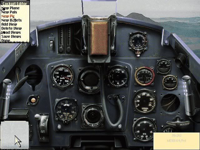
Similar to Col. Gibbon's Skunkworks Thread, I'd like to show you haw to make a new instrument panel as I go through all of the steps. Srea is working on a new version of the Me-163 and asked me to help, so I thought I would use this as my example.

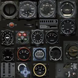
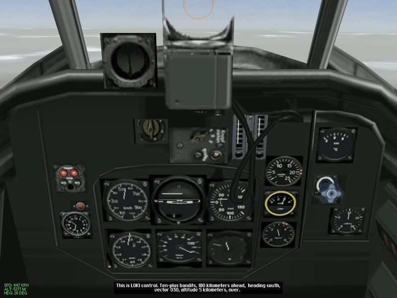
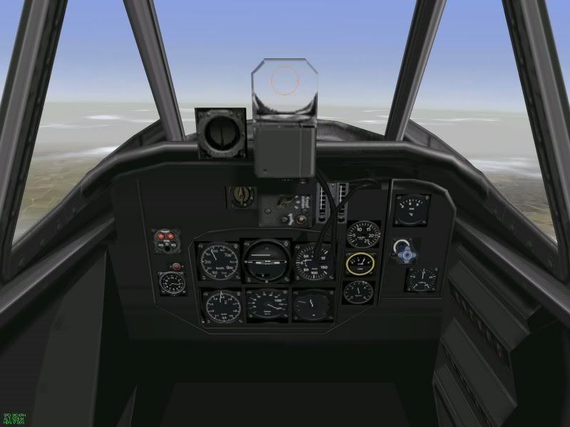
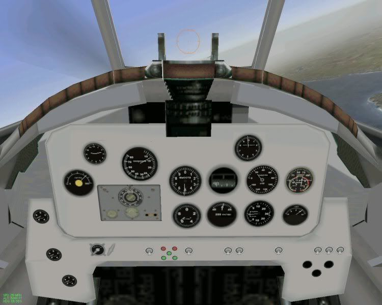
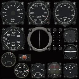
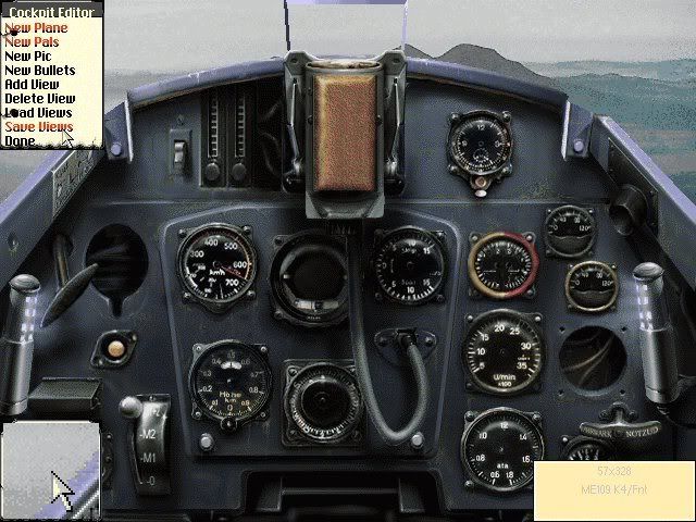
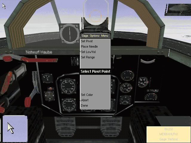
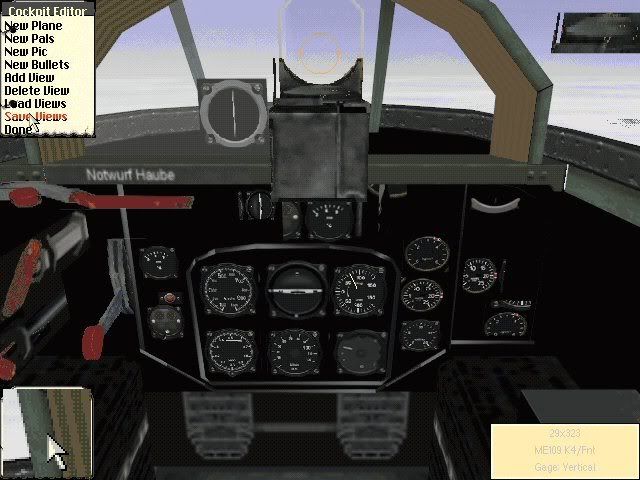
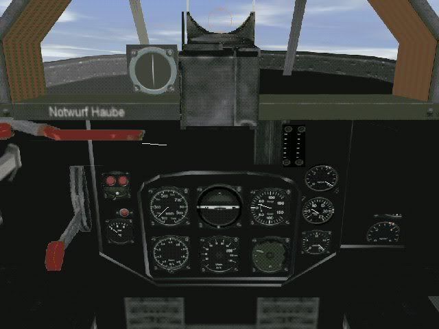
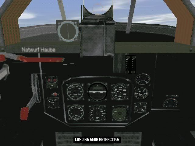
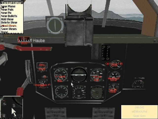
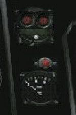
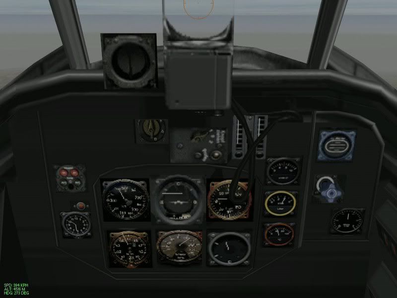
Sera sent me only the Instrument Panel file in the Me109K slot, which is the P109KX.3DZ and TPC file. I looked through my collection and found the aircraft he is starting with, which is the Firm's Me-163. I loaded up the panel with the rest of the model to see what I am starting with:


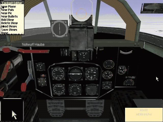
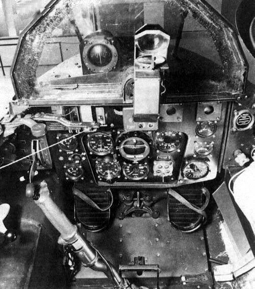
Pretty good for it's day, but some of the needles are off and the instrument faces are a bit fuzzy. The biggest question in my mind at this point is also, how accurate is it? So off to the web and other resources to find photos to see if I can confirnm this is a correct cockpit. I also have a considerable collection of research material on my hard drive, and I found a series of photos that confirm this is an accurate depiction of the Me-163:


When checking sources, I recommend going far beyond a single photo; make is a thorough search. Many times the configuration changes from one mark to the next. In Japanese cockpits, pilots were actually allowed to customize their cockpits to the extent of actually leaving out gauges! So, spend a few more minutes searching and your efforts will be rewarded.

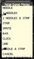
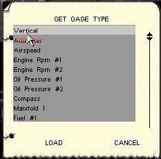
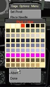
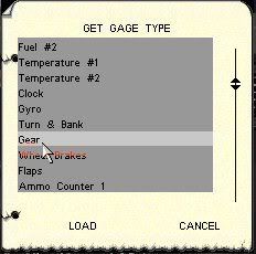
The next step is identifying the gauges. This can be difficult. Russian gauges in particular, as they are unique in design. I have an extensive collection of information and can be used as a reource if needed. I have also made a number of gauges available on my addon page at Tally Ho.

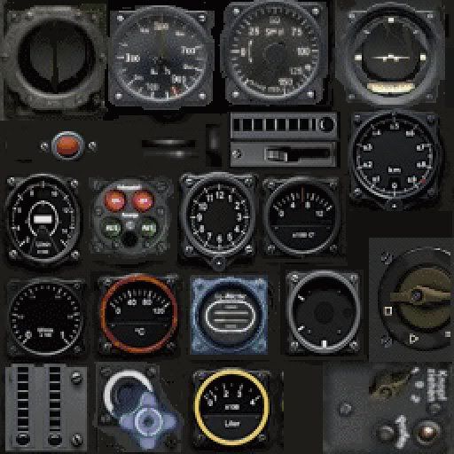
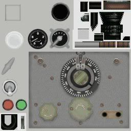
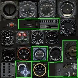
Going back to my references on my hard drive, I found this image:


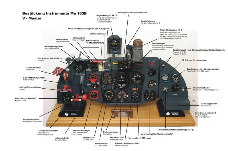
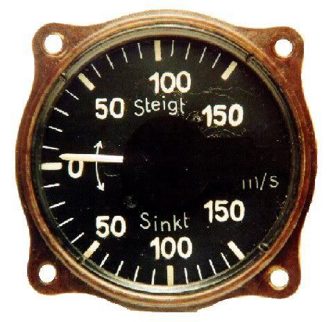
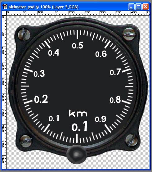
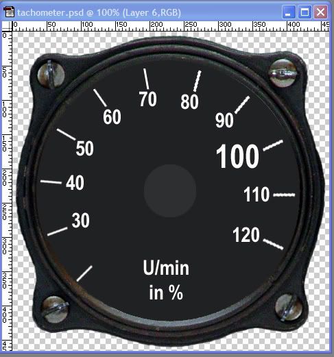
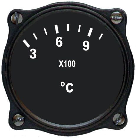
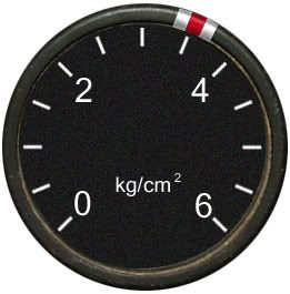
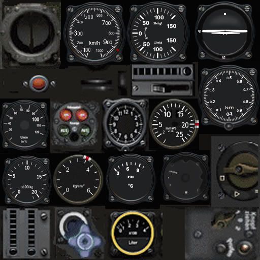
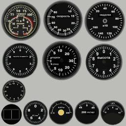
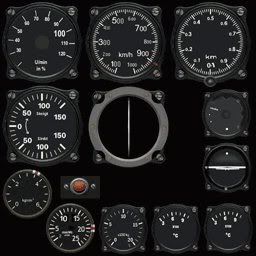
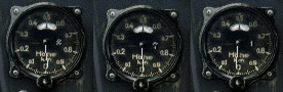
This is a remanufactured display version of the Me-163 cockpit, and although it is a bit too shiny and some of the stuff seems to be psuedo reproductions, the layout is correct and the gauges are for the most part original. (I'm sorry but I couldn't find the original website for these images.) Even on this site there were several alternatives for the blind flying panel, which is the central "raised panel" area with the most critical instruments mounted on it. In addition, this website had some great photos of the origianl instruments:


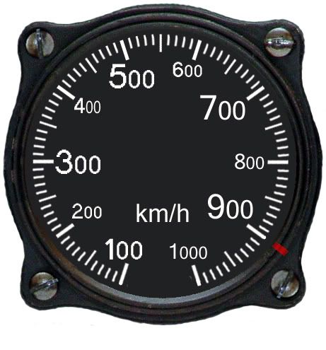
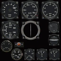
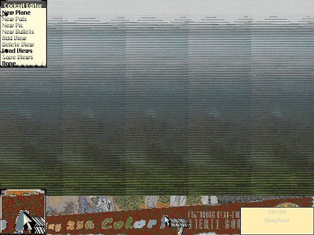
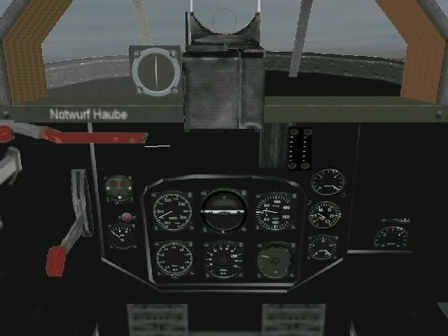
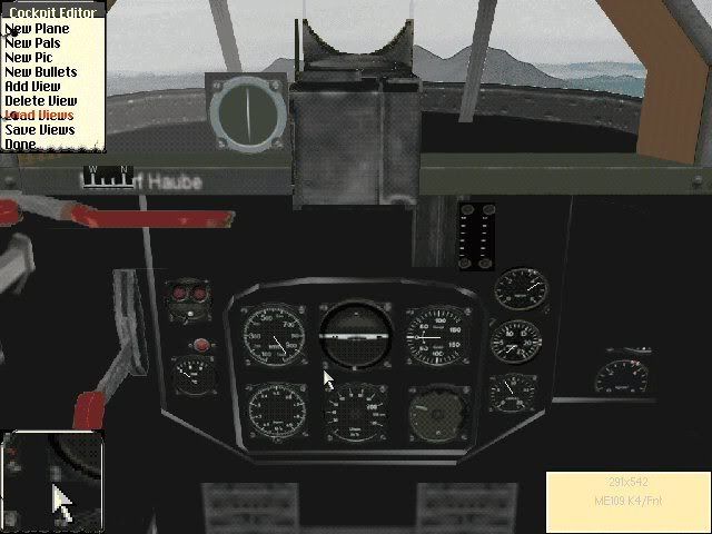
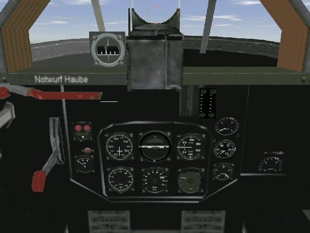
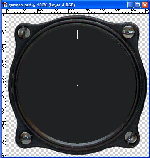
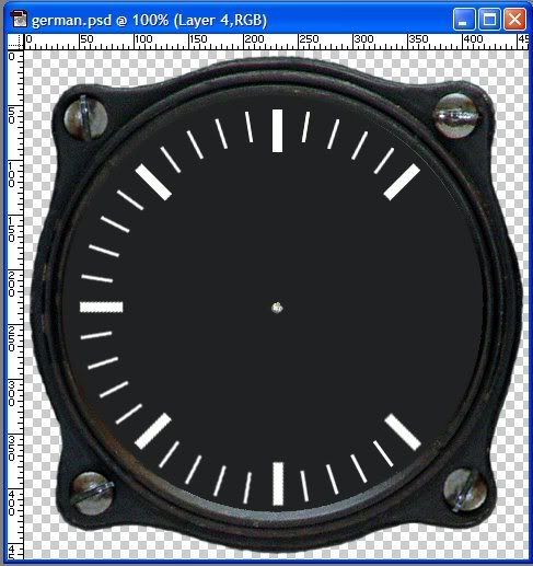
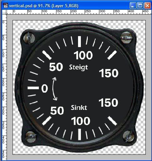
The urge to simply paste these images into the pcx file is overwhelming as they are fine close ups, so I airbrush out the needles and get rid of the white background, and give it a try. This is the result:


I would daresay the original looked better. There are a number of reasons why this simply doesn't work,palettes and conversion problems being the top two. But fortunately we can make our own - if you have Photoshop. The same technique may be available in Paint Shop Pro, but I have not investigated it.

I'll leave that for the next lesson.
Posted by: Fran_Zee

Re: How to Make an Instrument Panel - 01/09/08 04:55 PM

CJ, old friend, let me help you:

http://www.cockpitinstrumente.de/Flugzeu...%20Cockpits.htm

Go to "Jäger" (=fighter) then to Messerschmitt Me 163 - then you´ll get the different "Komet" versions. The page is in german, unfortunetely (for you ;\) ), I can translate for you if there´s need of

Good idea - I´m looking forward to yout workshop reports
Posted by: Ecv56SERA

Re: How to Make an Instrument Panel - 01/09/08 06:20 PM


Posted by: Crashin' Jack

Re: How to Make an Instrument Panel - 01/10/08 01:35 AM

Fan_Zee, thanks for the post; I already have that entire site pretty much downloaded, LOL! It's a truly awesome site, and I swear that at least part of it was in English when I first found it.

Sera, thanks for the images, I think they will be quite useful! You wouldn't happen to have an interpretation of the language in the last image, would you? Or at least which language?

The fourth image above also brings up a point I would really like to stress. I do not recommend using another game as a reference. I have found in other games that a certain license is taken to make things easier, cockpits are sometimes copied from one aircraft to another, and I have even found a Russian aircraft with gauges in English. I am not trying to put these cockpits down in any way, as they are all finely done, but personally I prefer to work from original World War II photos as my source. Sometimes the other games happen to provide a clearer view of something you know is correct, like trying to get the spelling correct in a language you are not familiar with. But if you are trying to be accurate, be skeptical! This includes WWII documentation. I always like to get at least one confirmation.
Posted by: Weird_Crapolla

Re: How to Make an Instrument Panel - 01/10/08 06:09 AM

Hi,

Language = Czech \:\)
So ... Pisis ... where are you .... ?

OFF
Posted by: Crashin' Jack

Re: How to Make an Instrument Panel - 01/10/08 06:11 AM

HOW TO MAKE A NEW GAUGE FACE

This is something that had really thrown me. How do you make a whole bunch of "tick" marks, following different radi, in a circle when you can barely draw a straight line? I found this thread which explained it all in a brilliant, simple way at a forum called "Simmers Paint Shop:"

http://www.simmerspaintshop.com/forums/general/471-making-gauge-art.html

I will expand on that idea in a minute. First I decide which gauge I want to do. Looking at my references, I have chosen the Vertical gauge, as it is symetrical, not too many tick marks, and pretty straight forward:


By the way, there are lots of good sources on the net for finding gauges, even of World War II vintage. There are many places that specialize in selling gauges as collector's items, for vintage aircraft, and so on. Even auction sites like eBay can yeild good results. All you need is something you can read.

The first step is to create the gauge case. Different countries tend to use a similar design; one case can go a long way! What you are looking for is a good case that has a nice combination of shadow and highlight detail, with a nice smooth finish. Select and cut or delete the background outside of the gauge away, as well as any open screw holes. If there are screws in place, leave them as is. Now carefully paint the inside of the gauge a very dark gray. Don't use black, as it is "too black" when you are done. Adding some noise to the dial face adds a bit of softness to it that is nice. I don't generally add any highlights to the gauge face; this hasn't worked so well when viewed "in game." We want to have very clear detail when we are through. Here is an example of a German case I have made using the above procedure:


Feel free to use this for your own projects! When you make a case like this, try to center it in the image as much as possible, and make SURE the image size is an odd number in both directions. now zoom in to the center of the picture, add a new layer to the image, and place a dot in the exact center of the image. Now you will have an even amount of space on either side, and top and bottom. Let's say your image is 201 pixels across and 215 pixels top to bottom. Now you have 100 pixels on each side of the dot, and 107 top and bottom. If your image was even, you would have 99 on one side, and 100 on the other, 106 on the top and 107 on the bottom. For the next step, this dot placement is critical or by the time you are finished you will have a skewed image.

In Photoshop, when I place the dot, I like to use the second smallest dot on the tool options menu; this dot is actually 3x3 pixels, is easier to work with, and will still be centered.

Now go to top dead center and draw a line for your first tick mark. You should have an image, that looks like this:


Now look at the origianl gauge. You need to determine what the degrees between each tick mark is. Don't worry, it's easier than you think. If you look at the vertical gauge, you'll notice that there is an area where the tick marks are missing on the right side. Since this gauge isn't a full circle gauge, we'll use the half circle instead. You can see there is a heavy tick mark straight up at the top, as well as one directly below it on the bottom. This is 180 degrees. Count the tick marks on the left side; you will see there are 20 tick marks (21 counting the top dead center; but we have made that one already). 180 divided by 20 is 9. So the difference is 9 degrees.

Go back to your new gauge in Photoshop, and select the dot in the center using the Magic Wand selection tool. Hold down the Shift key and select the tick mark as well. Create a new layer, and go to the menu bar under "Select," and choose "Transform Selection." Now you will have an image like this:


Look closely at the Transform Toolbar and you should see this:


Notice the two options circled in red. The one on the left is a series of boxes. This will change as you make you way around the gauge face. It is the relationship of the central pivot point - the dot - to the end if radial segment - the tick mark. This will be apparent when you come to it. To start, though, select the bottom center.

In the second red box, just after the little triangle, put in the degrees you want to turn the image. In this case, it is 9. As soon as you enter a value here, you will see your selection shift to a new position. You should now see this image:


Slect the Paintbucket tool, and a window will pop up asking if you want to apply the transformation. Click on "Apply" and paint the selected area white with the paintbucket tool.

To do the next tick mark, go to "Selection" in the toolbar meny, select "Transform Selection" again. Now you will see a wide rectangle. Do everything as you did before, except now in the small grid of boxes select the one in the lower left. "9" will still be the degrees.

There is an alternative to the above. You can go back to the original tick mark and dot, select them and add 9 to the degrees each time, so you end up with 9, then 18, 27 and so on. This can be more accurate, especially if you have very fine lines with a small degree of movement.

To move to the left of top dead center, use "negative" numbers, i.e. "-9" instead of "9."

I like to do the heavy tick marks after the thinner ones, but they are done in the same way; just use a larger step in between.

After a while, you should have an image that looks like this:


Now go back to the orginal tick mark, make a larger heavier one, and repeat the procees for the heavier marks. In this case, you will move the transform 9x5 or 45 dgrees for each mark. The end result should be this:


Now add in appropriate text, and the little up and down arrow, and you have this:


Note: I drew the arrow by hand, but there is a really great tutorial on drawing arcs here:

http://www.thegoldenmean.com/technique/pen3.html

So, there you go, one Vertical gauge ready to go. It is still in PSD form, and I hope you left all the layers as they were. You never know when you might want to use a part of it. Also, if you look closely, you will see that the tick marks aren't quite centered. Go through the layers and adjust everything up a little and it will look much better.

Store this gauge away and move on to the next. After you do this for awhile, you will have a pretty good library, and hopefully for the next project you only have to make a few gauges. Or better yet, send them off to Tally Ho for others to use!

Okay, I need a break. Give that stuff a go, and please post any questions.

Cheers!
Posted by: Ecv56SERA

Re: How to Make an Instrument Panel - 01/11/08 06:04 PM

I am impressed with their great work CJ!
Can you include this work inside the eaw?
Does the me163 have 13 active gauges approximately in the panel of instruments, can you make them to all with this technique and to include them inside the 256X256 pcx?
I am very retailer with my cockpits, in the case of the me163, I work a lot so that this it is real, at least in structure 3d, but you not to make good unstrumentos, their help is fantastic!
My work:


Posted by: Crashin' Jack

Re: How to Make an Instrument Panel - 01/12/08 01:36 AM

Sera, glad you like my work! It's a pleasure to do things when I know they are going into a great cockpit. I will do all the gauges, and maybe take a look at the other items on the pcx as well if that is all right.

Here is the new Altimeter:


This was done in the same way as the previous gauge. However, I did the tick marks in three stages, as there are three sizes to them. After they were all done, I had to fix some alignment problems at the bottom of the gauge, but they turned out pretty well and any remaining problems won;t be visible because of the reduced size.

To do the numbers, I had to use three different fonts. In Photoshop if you highlight some text you have written, then highlight the font option in the tool bar, you can scroll through the fonts by using the arrow key. If you find something really close, but not quite right, you can use it then go back with the pencil or paintbrush tool and make corrections.

The "km" symbol was a bit unique, I was able to lift this off the photo of the gauge and clean it up. I then selected it, and repainted it. This got rid of some off colors that would be a palette problem later on.

I also had to take some artisitic license with the small window that changes for every revolution of the needle. It had very fine graduations, and was located at the top where the 0.5 mark is. This doesn't exist in the EAW world and would likely be too small to be of use anyway. I will use the small window at the 3 o'clock postion we are all used to.

The next gauge I did is the tachometer for the gas turbine.


This one was much simpler to do as it doesn't have so many tick marks. Note also in the center there is a small black circle. On the real gauge this covers the spring mount for the needle; make sure when you do the needle for a gauge like this in the editor to set the proper offest. The needle shouldn't start in the center - there should be a gap between the pivot point and the start of the visible part of the needle. This will make more sense later on when we go through building the Pview file.

Cheers!
Posted by: Wudpecker

Re: How to Make an Instrument Panel - 01/12/08 02:46 PM

Jack--your work never ceases to amaze me.
Glad Sera has joined you in this project.
Posted by: Ecv56SERA

Re: How to Make an Instrument Panel - 01/13/08 02:16 AM

That beautiful work that you this making!
That makes me to make an effort but in my work so that the final result is it but real possible.
I am very happy of working in team with you, always admire their works.
I believe that we are in a good road and it will be a great cockpit!
Greetings and soon I will show my advances in the cockpit.
Posted by: Pobs

Re: How to Make an Instrument Panel - 01/14/08 10:36 AM

Lovely work guys, I am just praying here that this is the start of a cockpit making dream-team and that you will be looking at collaborating on some of the more common aircraft cockpits once you have done this one, some of the pacific ones are pretty basic at the moment for instance !!


cheers,


Pobs
Posted by: Crashin' Jack

Re: How to Make an Instrument Panel - 01/14/08 04:45 PM

I'm happy to work with Sera, he does some really outstanding work...Since he does the bulk of the 3dz work, it's really up to him. I should also tell you he sent me a 109E pit in the same folder.

Cheers!
Posted by: Pobs

Re: How to Make an Instrument Panel - 01/14/08 08:38 PM


Pobs
Posted by: Crashin' Jack

Re: How to Make an Instrument Panel - 01/15/08 04:02 AM

Okay, here are the rest of the instruments:

Temperture Gauge:


Fuel:


0-6 kg pressure gauge:


0-25 kg pressure gauge:


Airspeed:


AFN-2 Homing Device:


That's it for the working gauges with the exception of the Artificial Horizon. I'll finish that one up and hopefully show you how to put it all together tomorrow.

Cheers!

Posted by: Ecv56SERA

Re: How to Make an Instrument Panel - 01/15/08 05:29 PM

Magnifico!
Posted by: Crashin' Jack

Re: How to Make an Instrument Panel - 01/16/08 05:18 AM

As promised, here is the artificial horizon:


This is a bot of a strange gauge. As do many other artificial horizons, this one includes a ball type turn and bank indicator. But it ALSO has a needle, mounted at the bottom below the T & B ball, and the top points directly at the white spot at the top. We can now combine these types of gauges easily with the editor. You'll see that a bit later on. For now, I'm going to show you what to do with all the new gauge images.

First off, we need a PCX image to paste all of the gauges onto. For this project, Sera has already created a custom version for the Me-163. When starting from scratch, you need to find one and convert it for yourself. There are several ways to do this. The file you want is called P****X.TPC where the "****" is the name of the slot you are using. In the case of the Me-163, it is going into the Me-109K slot, so the file is called "P109KX.TPC." You can get the tpc file from an existing modded version easy enough, or you can extract one from the 3D.CDF file in the EAW main directory. To do this you need a file called CDFRW, created by Paulo Morais. It is available here:

http://www.sandbaggereaw.com/CORD/files/misc/cdfextractor.zip

Download and unzip the file. You will find two versions, one is CDFR.EXE and the other is CDFRW.EXE. The one with the "W" in it is the one you want to use, it has a user interface. The other version is a command line program. Click on the file to start the program and navigate to your main EAW directory. Click on "3D.CDF" and another window pops up listing all of the files in the CDF file. Scroll down until you find the one you want, and click "extract." You now have the TPC file extracted from the CDF. For ease of use, and to keep my EAW directory from getting too cluttered, I like to copy the CDF and program to a new directory and extract it there.

The next step is to convert the TPC file to a PCX format, so you can edit it in a paint program.To do this, you need a program called "TPC2PCX." It is available here:

http://members.aol.com/brokenputer/TPC2PCX.zip

I am not sure who created this particular program but it is essential for any modder. Unzip this program to the location of your TPC file and copy this line to a text file:

gpmTpc2Pcx.exe P****x.tpc P****x.pcx

Change the **** to the appropriate slot name and save the file as "tpc2pcx.bat". Now anytime you want to convert a TPC change the **** to the slot name, save, make sure the .BAT file, the TPC and the tpc2pcx file are all in the same folder, and in a moment you will have your PCX file!

The next step is very important! Don't do ANY modding until you save the palette! THis will help you get the colors right without too much trouble. I like to use Paint Shop Pro (PSP for short) for this step. Open the PCX in PSP and go to Image\Palette\Save Palette from the tool bar. This will open a new window; enter a name for the palette that will make sense to you, and click on "Save." Now after the images are added you will be able to easily recall and reapply the correct palette for the slot. You are now ready for editing!

So - here is the PCX as sent to me by Sera:


This is actual size! Pretty small, isn't it? The default size is 256x256. The first thing I is save the palette as "me163" so I can find it easily later. Now go to Image\Increae Color Depth and change the palette to 16 milion colors. Many editing features will not be availalbe unless you do this. At this point I like to move to Photoshop for the editing - I am more familiar with it than PSP, but I am sure all of this can be done in PSP as well.

I open the image in Photoshop and increae the size to 512x512. This makes it much easier to see and helps when you are lining things up and squeezing every last bit of space form the pcx. Now it looks like this:


Much easier to see. You can also see that the detail is a bit lost as well. That is to be expected when increasing a small image such a large amount. You may have noticed I kept the gauges I created very large. I like to have them in the 200 to 400 pixel range. Keeping them here ensures the maximum resolution when everything is shrunk back to the original size. I also save a copy of all of my images with the layers intact so I can "borrow" bits and pieces later to make other gauges, or make changes to the ones I already have.

Now it is a simple matter of resizing my new gauges and pasting them into position on the pcx. To help me with this, I like to use the "Opacity" option at the top of the layers window in Photoshop. Setting it to around 50% will allow you to move the new gauge into place and see if it is the right size. You don't want it to overlap any of the adjacent gauges. I also put each new gauge on it's own new layer. This helps a great deal if I need to move things around later. When you are satisfied with the new gauge position, you can black out the are behind it so none of the old gauge shows.

After adding all of the new gauges I now have this image:


Compare this to the image above. What a difference! As you add new gauges, try to put them in the same basic position as the original, but don't worry too much if they aren't exact. It just makes it easier to fine tune the needles later. In this instance, I have put several of the smaller gauges over other small gauges, as I am going to eliminate a couple of the gauges and create some new ones that are more appropriate.

Well, that's all for now.

Cheers!
Posted by: Ecv56SERA

Re: How to Make an Instrument Panel - 01/16/08 07:06 PM

Hola CJ!
Yo uso el PSP 6.0, el picpac, el tpc2pcx y algunos programas mas.
Hay cosas que no entiendo.
1) El EAW dentro del juego no me acepta texturas guardadas en tpc en 512X512, el EAW no las reconoce.

2) Hace unos años atras yo trate de que el EAW me aceptara texturas en 512X512, pero no logre hacerlo.
Esto ahora se puede hacer?

Si la traduccion estuviera mal y alguien lo advierte, por favor corrijanme, muchas gracias!
---------------------------------------

Hello CJ!
I use the PSP 6.0, the picpac, the tpc2pcx and some programs but.

There are things that I don't understand.

1) The EAW inside the game doesn't accept me textures kept in tpc in 512X512, the EAW doesn't recognize them.

2) I have treated behind that the EAW accepted me textures in 512X512 for some years, but be not able to make it.
This now one can make?
Posted by: Crashin' Jack

Re: How to Make an Instrument Panel - 01/17/08 04:59 AM

No Sera, EAW does not accept 512x512. Sorry, I guess I did leave that part off. What I do is increase the size to 512x512 to make it easy to edit, then decrease back to 256x256. That is the next part of the lesson. I needed to do some tests before I continue to make sure that my methods still made sense.

So, I left off with an edited PSD (the standard Photoshop format) image, though it is still 512x512. I did a comparison between reducing the image in Photoshop and in Paint Shop Pro. This is the result:


The image on the left was reduced and then converted to PCX in Photoshop. The image on the right was done in PSP. If you look closely, the PSP image is a bit brighter, but it is distorted. The tick marks on the gauges in particular don't come out well. I guess this is the reason I use Photoshop.

Now, to use the image in the game here is what you must do with the 512x512 image. Reduce it to 256x256. Do this before converting back to PCX or doing any palette changes. It is critical in keeping the image as sharp as possible.

Convert back to a PCX image. If you stayed in PSP and kept it as a PCX, this won't be required.

Open the image in PSP. Go to Image/Palette/Load Palette. Clicking on this will bring up a dialog box in which a pull down list is highlighted. If the name in this box is the palette you need simply click on "Load," if not scroll down to your palette first and then "Load."

You now have a PCX with the correct, 256 color palette. You may have noticed a bit of a color shift as you loaded a palette. You can pretty much count on this happening anytime you do this step - the critical thing is whether it did too much of a change. If so, you may have to rework the image with some filters or color changes to get the effect you want; I have never had it drift far enough to be of concern to me.

The problem now is that the game doesn't use PCX images, it uses TPC files. This is where PicPac comes in. This utility was actually released by MicroProse way back when to allow people to skin airplanes. I belive this is the only utility for the game ever officially released. If you don't have it, you can get it hereat Dumo's page at Tally Ho:

http://www.sandbaggereaw.com/RAFDum/PicPacFull.zip

Extract the files in the zip and you will get two folders, "Test" and "Patches." Open the "Pathces" folder and extract the zip file you find there. This is Picpac, but it is the command line version and is more dificult to use. Go to the "Test" folder and extract the zip inside it. Copy all of these files into the "EAW Textures" folder containing PicPac. Now use PicpacW. Thisis the Unser Interface version.

To convert a file in Picpac, click on "Add" and navigate to the file you want to convert. Select it. It will now appear in the white window in Picpac. Highlight it, make sure "TPC" is slected as your output option, then click on "Compress." In a few moments you will have a new TPC file in the directory. Copy this to EAW, and fly a mission. You should see your new creation!

Here is the origianl in 1024x768:


The new version:


Now in 1600x1200:


Note to Sera: I still need to move things around a bit in 3DZ Studio, so don't worry about the placement, LOL!

If you load up your new panel and everything is black, you forgot to load the original palette. If the game crashes, you forgot to resize the image.

You will notice that there is some improvement in the gauges, especially the smaller ones. You can improve things quite a bit if you are willing to move some stuff off of the X tpc on to others, such as the V tpc. For example, in the LaGG 5 panel I did this is the tpc:


The ONLY thing on the X.tpc are the gauges. This allowed them to be much larger in size. I moved the "detail" stuff to the Plag3v.tpc which was associated with the Z.3DZ file (and could have easily just been called the Z.TPC file):


The end result was this panel:


The detail is pretty nice, I was very pleased with the result. By rethinking the way cockpits are made, there can be an astonishing amount of detail added. We have available for use the V, W, X, and Z 3dz files, which means we also have the V,W,X,and Z tpc files to add detail to. We also have the Y 3dz and tpc for the prop that I am sure can be utilised, and then we have the U files for the wingviews that are nearly empty -- although they are not affected by the cockpit lamp. The V and W files are used for the left and right halves of the cockpit and contain huge amounts of unused space. They can be combined to just the V files and leave the W files completely open.

Next time we'll look at the cockpit editor and how it works, and we'll make a new P***VIEW.CPT file, from scratch.

Cheers!
Posted by: Ecv56SERA

Re: How to Make an Instrument Panel - 01/17/08 10:01 PM

Now if I understand!
You something could make similar to the lag with the gauges of the me-163 assigning the gauges to the file p109kx?
I could incorporate other objects inside the W OR V I would not have problems in that, because there I have more than enough space.
Cheers!
Posted by: Crashin' Jack

Re: How to Make an Instrument Panel - 01/18/08 03:27 AM

Sera, that would be great! I would say move the areas marked in green to the Z.tpc:


I will rearrange everything else. Oh, and here is the new compass; I think it is the one you wanted?


Cheers!
Posted by: Crashin' Jack

Re: How to Make an Instrument Panel - 01/18/08 03:07 PM

I have now moved everything around on the pcx, increased the size of most of the gauges and came up with this image:


Resizing and converting to a pcx left me with this image:


I am pretty satisified so far. The detail is still clear, and I still have room to add the ammo counters and possibly a few details.

The next step in creating a cockpit is to use 3DZ!Studio for Windows to put everything in it's proper place. It is available at Gurney's page here:

http://members.fortunecity.com/gurney/download.html

I won't go into general use of the program unless someone requests I do so. I moved all of the gauges around until I was satisfied with the position of everything, and I also nulled out most of the things that are not gauges. I left the edges of the panel in place as guides, but these will also be removed to the "Z" files:


The area with the red dot is for the ammo counters, and the area with the green dot should have a gauge as well, but I haven't determined what this gauge is exactly. It is called in German "druckmesser fur hohenatemanlage" and my translater gives me this: "pressure gauge fur high breath plant," (Fran, can you help me out here?) which leads me to assume this to be the chamber pressure for the rocket motor, something not modeled in EAW.

I save the new 3dz file and copy it into EAW and start a mission to view my new creation AND!!!! A huge disappointment. I only see the compass and a bit of what should be the ammo counter. However, this can be fixed. Back into 3DZStudio, I load the 3dz and use the center mover. This is a great little tool; it moves the ENTIRE 3dz file in all three axis. It takes some trial and error, moving the piece around and checking in EAW for final placement (Rotton50 made a version for me that shows the entire cockpit and this step is easier; but this is not a generally available mod so I did it the usual way.)

The result:


Compare this to the earlier version, before I trimmed away the excess detail:


Definition is definitely improved! Some adjustments are still required, and I need to add a few things like the landing skid indicator and the ammo counters. Then we will be ready for the new Pview file. By the way, these images were done in 1024x768 but my image host scales them down to 800x600.


Cheers!
Posted by: Rotton50

Re: How to Make an Instrument Panel - 01/18/08 04:20 PM

CJ,

Please, if anyone wants that STUDIO mod, let 'em have it. The more people you interest in this process the better.
Posted by: Ecv56SERA

Re: How to Make an Instrument Panel - 01/18/08 06:12 PM

CJ, que necesita que yo haga?
Magnifico trabajo, me gusta mucho!
Usted deme una url para bajar sus nuevas creaciones en pcx, asi yo puedo continuar el cockpit, como escribi antes, usted digame que puedo hacer.
Saludos!

---------------------------------------

CJ that needs me to make?
I magnify work, like me a lot!
You give me an url to lower their new creations in pcx, I can continue this way the cockpit, like I wrote before, you tell me that I can make.
Greetings!
Posted by: Wudpecker

Re: How to Make an Instrument Panel - 01/18/08 09:34 PM

CJ-- What about luminous lights on the panel?
Do the red lights shine at night?

(Incredible work-- in the true meaning of unbelieveable )
Posted by: Crashin' Jack

Re: How to Make an Instrument Panel - 01/19/08 01:32 AM

Ray, thanks, will do for anyone that asks; should maybe send it off to Mike?

Wudy, thanks mate, I appreciate the kind words. As for luminous? They ARE sprites...haven't gotten to the Pview yet. ;\)

Sera, if you could send me the Z.3dz and TPC files I will move eveything I can to them....
Posted by: sydbod

Re: How to Make an Instrument Panel - 01/19/08 02:43 AM

Hi C.J.

I have always been interested in working approaches to sharpen up images once they have been rescaled.

Have you found a good way of doing this.
I tried to do it manually on only two of your gages (but not very good attempt)


This is a great tutorial that you are making \:\)

EDIT: yes..yes..I know, I am about as artistic as a Drop Wombat.(save some one else from having to mentioning it)
You happy now Jelly \:\)
Posted by: Rotton50

Re: How to Make an Instrument Panel - 01/19/08 02:47 AM

CJ,

This is your baby so I think you should add the cockpit program on your pages. It will probably get more exposure there.
Posted by: MrJelly

Re: How to Make an Instrument Panel - 01/19/08 03:41 AM

Syddy- a wombat or a drop wombat? We never told Ralf about those!

Just about to leave for the airport- see you next week!

Jel
Posted by: Crashin' Jack

Re: How to Make an Instrument Panel - 01/19/08 04:47 AM

Ray, gotcha, will drop a line to Mike. Thanks!

Sydbod, I guess that's one reason why Photoshop is so expensive; Paint Shop Pro is a great program, I use it for many things, but Photoshop is much better at file conversion and scaling. That is one part of it.

A long time ago, I read something that has always stuck with me. It was in some sort of tutorial, but it talked about using the BLUR tool to sharpen an image. I have messed around with it over the years, and though it seems wrong, using the blur tool first and then the sharpen tool sometimes clears things up. I think it's because it reduces pixelation by blending the image a bit, then use the sharpen tool to straighten it up. This must be done in very slight amounts, but I have managed to use it to clear up black and white images from WWII to help me read the text on cockpit features. It doesn't work too well on smaller images, because the effect is lost due to the much lower pixel count. I haven't gotten the technique to work very well at all on the smaller ones.

When I create images for the gauges, I always keep them in PSD form and very large, and I reduce them, merge the layers, then drag them onto a new PSD (not pcx) to get the sharpest image. Then I reduce the image to 256x256, and only then do I convert to a PCX.

There is one other thing that can affect the resolution of the gauges. When you are fixing the final position in 3DZ Studio, the closer they are to you (the closer to 0 on the X axis) the larger the gauge will be, and the clearer the image in game. This only works so far, though because if you move them too close, it feels like you are sitting in a very small cockpit indeed.

Well, I must go off and prepare the next lesson.

Cheers!
Posted by: Ecv56SERA

Re: How to Make an Instrument Panel - 01/19/08 01:43 PM

CJ:

http://www.ecv56condor.com.ar/modules/NS-Alas/eaw/files/163.zip

The files p109kw, p109ky and p109kv are not finished.
P109KW: They lack to locate erased elements of p109kx.
P109KV: It lacks to extend the protection glass toward the right, because p109kw.pcx doesn't have transparency.
P109KY: It lacks to finish the glass bubble.
Posted by: Crashin' Jack

Re: How to Make an Instrument Panel - 01/20/08 03:58 AM

Sera has just sent me a package with his cockpit in its current state. I added the TPC I made (he did one from the image online.) I was amazed how it turned out!


This aircraft is a very small plane, only 18.67 feet (5.69 m) and the cockpit is TINY! Wow, do you get that feel in this cockpit. You still get a nice view around, and tons of detail. Awesome job, Sera!!! I am going to resist showing you more, becuase you need to see it in 3D for yourself.

Cheers!
Posted by: Ecv56SERA

Re: How to Make an Instrument Panel - 01/20/08 09:16 PM

Thank you CJ!
Can you accommodate the needles in the gauges?
Does the me163 have a single indicator of ammunition, that you can correct?
Can you send me their work when this ended one? in that way I can continue the cockpit.
Again thank you!
Posted by: vonOben

Re: How to Make an Instrument Panel - 01/21/08 12:24 PM

Thanks for this tutorial Jack .
I hope we will se new EAW cockpits as a result ;\)

Cheers
Posted by: Crashin' Jack

Re: How to Make an Instrument Panel - 01/21/08 04:44 PM

Thanks Per, I hope to see a few more people become involved as well!

Sera, I made some changes and added the ammo counters and the landing gear indicater:


I just need to map the locations and it's good to go.

Now, I'm going to take you through the steps for editing the new cockpit. First we need a new image of the instrument panel view. Ideally we want this view without any of the needles and sprites floating around the cockpit so we can have a clear view. So first we will create a new Pview file without any instruments in it. You will need the Cockpit Editor installed now. It is available at my addons page at Tally Ho:

http://www.sandbaggereaw.com/crashinjack/CockpitEditor12CE.zip

The readme gives instructions on installing the editor. I would definitely recommend a clean install!

First of all, back up your "cockpits" folder that was installed by the editor. We are going to be creating a new cockpit, so whichever cpt file you are creating is going to get overwritten. The editor does make a backup copy, but if you hit save again you will have lost the original.

Start the game, and when you get top the main screen use Ctrl-E to start the editor. You should see a screen that looks like this:


Go to the main menu in the top left and select New Plane:


Choose the nationality of the aircraft slot:


Then choose the specific slot:


This will automatically load all of the default images for this slot, but anything that appears inside the cockpit will be black. This is okay! Now we need to add the palettes. Select New Pals from the Main Menu:


This brings up the Palette Menu. Select the Day Pal slot:


This brings up the Col Menu. "Col" is the extension of the palettes used as building blocks for the program. Select the proper DayFade col, in this case for the Germans:


Click on Load, and you will be returned to the palette menu. Select the other two palettes, then click on Load in the Pal Menu:


This will load all three palettes. You should now see everything in the cockpit in full color:


Click on "Save Views" as shown in the above image. The cursor will lock up for a few moments while the new Pview file is created. Now click on Done:


This will exit the editor and take you back into the game main screen. Go ahead and exit the game. Now look in the "cockpits" folder and you should see a new Pview file for the slot you are using. Copy this into the main EAW folder. Also put your new cockpit files into the folder - these shuld be for the new 3DZ cockpit you are creating. Go to your EAE.INI file and change the size to 640x480. This is very important, as the editor only works in this size.

Go into the game, and fly your new aircraft. When you are in game, hit Ctrl-F1. This will bring up the 2D instrument panel view. Now hit F8. This will change the view to the virtual cockpit, but still looking at the same spot. DON'T TOUCH YOUR MOUSE!!!! Don't change the view in any way. Wait for a moment when there are no messages on the bottom of the screen - the hud in the lower left is okay. Take a screen shot - for me this is hitting the "Print Screen" button - and exit the game.

There should now be a new image in your main EAW directory called something like SCRN0001.BMP. Open this in PSP (or alternatively, simply start PSP and hit Ctrl-V - this will load the clipboard directly into a new image) and go to Image/Palette/Load Palette. Load the palette you saved long ago from the original cockpit - in my case this was the me163 cockpit palette.Save the image as a PCX. Exit Paint Shop Pro.

Copy your new PCX image to your Picpac folder and start Picpac. Remove anything shown in the white window on the right, and add your new image. Now select the USER option as the default output extension and THEN deselect "Save Palette." The image has palette info, but you don't want the actual palette attached. Compress the file. This should result in a new "pic" file in your Picpac directory.

You need to rename the image so that the editor will be able to load it. The convention is "P**##L.PIC" or "P**##H.PIC." "**" is the slot, and "##" is the view. "L" is the normal type of view, and "H" is the 45 degree up view. You don't really have to make the numbers and H-L right for this step - that is only needed for the autoloading feature - But you DO have to follow the convention. I have found numbers up to 33 work in the first two (most numbers up to 24 are in use - use something higher) and anything between 11 and 17 works for the second set, the view numbers. I have been using "P3311L.PIC" for my work. Rename you pic file and copy it into the "pic" folder in EAW used by the editor.

Now, restart EAW and go into the editor. Instead of doing all of the steps we did before, use the "Load Views" option on the Main Menu:


This brings up the "Load Cockpits" menu. Scroll down to the one you created earlier - in this case it is the P181VIEW.CPT, the Pview file for the Me-109K:


Now your screen should look something like this:


Select "New Pic" from the Main Menu as shown above, and the "Load View" menu appears:


Scroll down to the new pic file you created, and load it. Your new view should be loaded:


Click on "Save Views" and your new view is now part of the P***VIEW.CPT file you created, and will be used when you use the 2D view in 640x480. You could use the same procedure to create all of the rest of the views as well, but you would also have to create sprites to use for the canopy rails when looking straight ahead.

All of the instruments will now be blanked out with one exception. The Artificial Horizon will still be active in-game as this is controlled by the VCG****.DAT file - the only gauge set up this way.

Now you have an image suitable to do your editing on. Now you should be able to add all of the gauges and line them up properly with out having to go back and forth from the editor to ingame, make an adjustment, repeat, etc.

Well, that's all for now folks!

Cheers!
Posted by: Crashin' Jack

Re: How to Make an Instrument Panel - 01/24/08 03:04 PM

ADDING A NEW GAUGE

Now we are ready to add a new gauge to the cockpit. Start the game and open up the editor. Load the Pview file you are working with by clicking on "Load Views" in the main menu:


Scroll down to your cockpit file, click on it and press "Load." Your new cockpit will appear on the screen:


To create a new gauge, press "Alt G" to bring up the New Gauge menu:


Most of the names should be obvious if you think about the gauge you want to make. An airspeed indicator for example is a needle, a compass is a strip, landing gear or flaps are a sprite, ammo counters are a bar. Play around with these a bit and you will see what is what.

A note here about some types of gauges. I have not been able to get the strips working. These are for Gyro 1 and Gyro 2, and the strip for the Altimeter. All of the other sprites use a similar format, they are either a single picture or a series of pictures. But the strips are meant to scroll. I have not been able to properly extract these gauges from the CPT file to work with the editor, but I can show you how to add them manually with a hex editor. It really is very simple to do, so don't worry. I will show you how to do that in one of the next lessons.

In the meantime, if anyone has further info on these types of sprites, I would love to hear about it.

So, select the type of gauge you want to do and click on the appropriate type. We are going to make a Vertical indicator, so I click on "Needle" as it uses only one needle. This brings up the "Gauge Type" menu. Here I click on "Vertical" then load it:


This causes the "Gage Status" Menu to appear:


I am making a German cockpit, so I click on "Metric Gage." It does not go counterclockwise or full circle, and it is not non linear, so I click on "Done."

Before we go on I want to point out a problem with the cursor arrow. It does not place things using the tip off the needle as you would expect. It uses one of the "wings" of the arrow. Look at the image below, and see where the red arrow is pointing to:


I haven't been able to fix this yet. So, keep this in mind as you make a new gauge.

You should now have the "Gage Options Menu" on the screen. Click on "Set Pivot." This sets the center point of your gauge. So, using the cursor, place the center point on your new gauge. Use the zoom window in the lower left for the best view:


Now click on "Place Needle." This will create a long needle up to the default upper left corner of the screen. Move the cursor to the point you want the needle to START at. For the Vertical gauge, this will be the lowest angle it will display during a dive.

Now the program will ask for the "End Point." This is the highest value during a climb. Finally it will ask for "Offset." This is the area between the center of the gauge and the start of the needle. Many types of gauges have a small cover in the center; this simulates that feature. Move the cursor up and down to increase or decrease this amount. Click when you are satisfied.

The last option is "Color." This sets the color of the needle:


Choosing the second color, the white, should give you a white needle in game. The first color shows cream in the editor, but pink in game, and the third comes out black. I need to investigate this further.

Congratulations, you have created a new gauge! Try it out in game if you like, just remember to save the view first:


Thats all for now, folks.

Cheers!
Posted by: Fran_Zee

Re: How to Make an Instrument Panel - 01/24/08 05:15 PM

You´re doing a terrific job, CJ - my admiration

A stupid qustion, btw - is somebody doing a Me 163 3dz for the xterior plane?
Posted by: LLv34_Doc_1

Re: How to Make an Instrument Panel - 01/24/08 06:59 PM

tutorial saved thanks...
Posted by: Crashin' Jack

Re: How to Make an Instrument Panel - 01/25/08 01:49 AM

Doc, thanks for saving it mate, there will be more coming - a lot more!

Fran, I chose to use the Me-163 specifically because Sera is doing a new one, and asked me to do the gauges. I thought it would make a great example, as the mix of gauges needed doesn't exist in the default EAW world. For example, the artificial horizon has an additional needle for the turn and bank like that used in British aircraft - but just the top needle. I can do that with ease with the editor.

Check this thread for Sera's original post concerning the Me-163:

http://www.simhq.com/forum/ubbthreads.php?ubb=showflat&Main=256191&Number=2393051#Post2393051

Cheers!
Posted by: Crashin' Jack

Re: How to Make an Instrument Panel - 01/28/08 01:50 AM

I've gone ahead and put in most of the needles - the airspeed, vertical, tachometer (although it's not showing; I need to trouble shoot that as it was working in an earlier version) fuel, oil pressure and vacuum. The oil pressure and vacuum aren't really correct for the Me-163, they should be chamber pressure 0-6 kg and 025 kg, but this is not modelled in the game so I substituted these. I did a test flight and it looked like this:


Some of the needles aren't quite right but that's okay, we can edit them later. You will also notice there is a white line to the left of the bottom left of the gunsight. This is the artificial horizon. This is not modded with the Cockpit editor as it is from the VCG file. This is the ONLY needle or gauge that has it's data fully in the VCG file; the rest of the data is placement and scaling for the 3D cockpit only. However, we must go through these steps to build up the new panel's instruments.

The next thing to add are the sprites. I want to add the sprite for the landing gear. So I start the editor, load my view, then hit Alt-G to add a new gauge. This time I select "Sprite." This brings up the "Get Gage Type" screen, I select "Gear" and load it:


This brings up the "Gage Options Menu" which we've seen before but now because we chose a sprite for the gage type there is only one option - "Load Sprite:"


Clicking on this brings up the "Load Sprite" selection menu. I scroll down to the sprite for the landing gear, select it and load it. The menu is replaced by the "Gage Options Menu once again, except this time there are two black bars. There should be text here; I'll have to fix that in an upgrade. If you click on the one just below "Load Sprite" it turns red:


This also brings the new sprite on the screen in the upper left corner and the text "Place Sprite" appears on the Menu:


When You are happy with the placement, simply click the mouse button. Now go to the "Gage Options Menu" and when you mouse over the lower black bar, it turns red. This is the "Done" button:


This closes the Gage Options Menu and you are ready for the next edit. Don't be surprised when your new sprite disappears. The editor doesn't show the active stage of the sprite.

Don't forget to "Save Views" when you are finished and ready to leave the program - otherwise all of your new work is lost!

Here is a shot of the gauge with the gear extended:


And retracting:


Cheers!
Posted by: Crashin' Jack

Re: How to Make an Instrument Panel - 01/28/08 04:43 AM

For the next step I want to add the Gyro type compass to the left of the gun sight. At the time of this tutorial, I have not yet been able to get the Gyro or Altimeter strips to work. But that's okay, because we CAN add them manually. For this you need to use a Hex Editor. Don't woory, it is fairly easy to do. If you can use search functions, copy and paste, then you are all set. You can find many excellent hex editors on the web that are free for use. One ou might try is by HHD Software. They have a free version that will open files up to 10 megs, which will be fine for pretty much everything in the EAW world you might want to edit as long as it is extracted from the CDF file first.

In addition, you will need the gauge extracts from my page at Tally Ho:

http://www.sandbaggereaw.com/crashinjackadd.html

Towards the bottom under the heading "Cockpit Files (for 3dz Modding Only)" the column on the left contains links for each slot's gauge files. Download the set you need and extract them to a folder. You will find all of the gauges, each in their own folder, as well as a readme that is actually the gauge header table for that slot.

Start your Hex Editor and open the Pview file you are working on. I like to resize my editor so I can open Notepad or Wordpad alongside of it with the header table displayed for easy access. The first thing you need to do is find the gauge section. This can vary, especially since we are creating our own file. The originals followed the same sequnce more or less, but there were some significant differences that leads me to believe it depends on what order you do things in.

The best way to find the gauge section is to look at the header chart and find one of the instruments you already added with the editor. Look at the line below the name of the instrument and you will see two sets of four digits each. Find one you have already added that is more than, say, 0000 0300. This is a common number. In my case, I have added the landing gear sprite. In the header table for the 109K slot, the lines for the gear look like this:

*Landing Gear
0400 1100 C044 9D01 0000 0000 0000 0000 0000 0000 0000 0000 FFFF 0000 0000 0000 0000 0000 0000 1F00 3A00 6502 0000 0000 0000 0000 0000 0000 0000 0000 9C06 0000 0000 0000

"0400 1100" is what you are looking for. Lots of the other numbers can and will be different, but these are identifiers for the gauge. They are more complex and likely to not appear too often in the code for the file. So I do a search for "04001100" (take the space between them out!) and I find some code like this:


I've shaded in the area the cursor stopped at as the cusror didn't show up in the screen shot. I did another search from this point and the editor cycled around to the same spot, so i am sure this is it. In addition, if you look 2 lines down in the center, there is a "1F00." This is present in ALL gauges - it's the needle color. Since you didn't change the needle color on the sprite (you can't in the editor because there IS no needle) but it is there none the less, and a good flag that this is the gauge we are looking for.

The rest is really easy to do. Looking in the gauges I have for the 109K slot I see....that the Gyro isn't there! That's okay, the 109k didn't have one - at least not in EAW. So I go looking for a replacement. If you did your homework, you know what the gauge SHOULD look like. Simply find another aircraft that has the type you need. You can see it in this image:


It's the thing to the left of the gun sight. It is the single scale type, like the ones in the P-38s. So I go back and download the gauge set for the P-38H. After extracting I see not one, but TWO Gyros listed. Which is the one I want? If you make sure your resolution is set to 640x480 and pop into the game for a moment, set up a mission for the P-38H and when the screen comes up hit "Alt-F1" all of the gauge names will be displayed. I see the one I want to try is "Gyro 2" so I open that one up in the hex editor, copy the entire file, go back to my Pview file and paste it in just before the landing gear I found earlier.

There is one more step. You must increment the gauge counter. That means you have to find the gauge count bytes and add one to it. AH! But I know where it is. Go to the very top of your Pview file in the hex editor and go to address 280. My Pview file has 07 at this address, so I change it to 08. I save my file in the "cockpits" folder in EAW and start the Cockpit Editor again. I look around and just under the main menu I see the Gyro:


Now I need to move it to it's proper place. Hit "P" on the keyboard and all the existing gauges will have a gray bax around them. Hitting the "G" key puts a red box around the first one, then toggles it's way through the rest of the gauges. Keep hitting it until the Gyro is highlighted:


Now press "Alt-E" to bring up the "Gage Options Menu" and click on "Place Sprite:"


Now you will see that it asks you to "Select Strip Area Upper Right Corner." This SHOULD read "Select Strip Area Upper LEFT Corner." That's another thing that will be fixed in the next release.


After clicking on the spot you want to be the upper left corner, it will ask you to place the next corner,. Again, this is screwed up; place the lower RIGHT corner:


Clcik on "DonE" and you will see this:


Save the Views, exit the editor and game, copy the new Pview over and go for a test fly:


There it is! (I can see I'll have to repaint that gyro case a bit darker!)

So, as you can see once you find the location of your gauges in the Pview file, the rest is pretty simple and the final editing is easy as well. In fact, now you know how to go back and tidy up any gauges that aren't quite right!

Cheers!
Posted by: Crashin' Jack

Re: How to Make an Instrument Panel - 02/02/08 02:24 PM

I have now added a few of the other gauges, including the ANF2 Homing Device, two Ammo Counters (which use the "bar" instead of needles, and also suffer from the same "Upper Left" and "Lower Right" problem as the sprites) and I put the tachometer back in.

A note on the homing device. There are several types of these in use in the game. The German ANF2 uses two needles but they are seperate gauges. If you scroll to the bottom of the gauge menu, you will see "Homing Indicator X" and "Homing Indicator Y." This is the set you should use.

If you look at the panel there is a small indicator light just below the landing gear indicator:


I want this to be the ignition for the Me-163. The problem is the one for the Me109K is a lever type of sprite, not a light. So I go into the game and check the various aircraft until I find one I like. The P-47C has a nice one, so I will use it. However, you can't call it up in the editor because it doesn't have the correct name. The editor will only call up sprites with the name "P18**" for the Me-109K slot which uses the P181VIEW.CPT file. So I go to the P-47C collection of gauges, which begin with "P02" then copy and rename the "P0211_IGNT_1.SPT" sprite to "P1811_IGNT_1.SPT." Make sure you have a bcak up of the original gauge!

To add the new sprite, go through the same steps as we used to add the landing gear.

After adding the gauge I notice once again that I will have to make a small adjustment to the size of the original image as the sprite is a bit larger. I like to save all of the fine tuning for the end and do it at once, after getting everything installed and working. Sometimes you make an adjustment in one spot, then find later you have to readjust it because of something else, so I suggest waiting.
Posted by: Crashin' Jack

Re: How to Make an Instrument Panel - 02/03/08 06:32 AM

Now it's time to add the altimeter. This is another of the couple of gauges I haven't been able to make work. The problem is with sprites that scroll rather than just flip from one image to the next. The headers are different and I haven't been able to get that part to work.

As you may or may not know, the altimeters in EAW are made up from either one or two needles, and a sprite that indicates passage through 10, 20 or 30 thousand feet - or meters for the metric gauges. It is this sprite that has given me trouble. Here is a view of the altimeter in the Me-109K:


In this sequence you can see the sprite change from the hasmarks through to the 1 as the aircraft passes through 10,000 meters.

The function of this gauge can once again be added by using the hex editor. Use the header table to look up an instrument by searching for it's id code, then copy and paste the gauge in from the 109K collection of gauges into the Pview file just before whichever gauge you find. Save and go into the editor and edit the locations of the needle and the sprite and you are done!

This pretty much sums up the Me-163 cockpit in the 2D world. The next step will be to mod the VCG109E.DAT file so everything shows up correctly in the 3D cockpit.


By the way, we have passed over a thousand views for this tutorial. I am quite pleased and I thank you all for taking the time to read it. I hope to see some of you give it a try!! If anyone has any questions, please send me a PM and I will try to help you out.

Cheers!